
Product Description
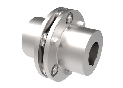
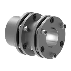
WGP Drum Gear Coupling(JB/T7001-2007)
WGP Drum Gear Coupling With Brake Disc has a brake disc, brake disc can rotate speed by controlling the speed to adjust the machine. As shown in figure WGP with brake drum set type gear coupling is divided into I type and II type 2 forms, the only difference is that the brake disc is different.
WGP Drum Gear Coupling With Brake Disc is an improved type of gear coupling, consisting of inner gear and the same number of teeth of the flange half band coupling parts etc..
WGP Drum Gear Coupling With Brake Disc at work, 2 have the relative angular displacement, relative axial sliding periodic internal and external gear tooth surface, will inevitably lead to tooth wear and power consumption, therefore, the gear coupling needs to work in good condition and seal. The toothed coupling has small radial size and large load capacity. It is usually used for shafting transmission under low speed and heavy load conditions. The high accuracy and dynamic balancing gear coupling can be used for high speed transmission.
·WGP Drum Gear Coupling Main Dimension(JB/T7001-2007)
| Type | Normal torque Tn/N·m |
Shaft hole diameter d1,d2,d3 | Shaft hole length (L) | D0 | D | D2 | D4 | B | F | N | C | C1 | C2 | C3 | |
| Y | J1,Z1 | ||||||||||||||
| WGP1 | 800 | 12,14 | 32 | – | 315 | 122 | 98 | 60 | 58 | 30 | 38 | 30 | – | – | 2 |
| WGP2 | 1400 | 22,24 | 52 | – | 315 | 150 | 118 | 77 | 68 | 20 | – | – | |||
| WGP3 | 2800 | 30,32,35,38 | 82 | 60 | 355 | 170 | 140 | 90 | 80 | 49 | 3 | 23 | 25 | ||
| WGP4 | 5000 | 40,42,45,48 | 112 | 84 | 400 | 200 | 160 | 112 | 90 | 45 | 3 | 29 | 17 | 3 | |
| WGP5 | 8000 | 80,85,90 | 172 | 132 | 500 | 225 | 180 | 128 | 100 | 45 | 3 | 41 | 19 | ||
| WGP6 | 11200 | 100 | 212 | 167 | 630 | 245 | 200 | 145 | 112 | 44 | 5 | 48 | 20 | ||
| WGP7 | 16000 | 100,110 | 212 | 167 | 710 | 272 | 230 | 160 | 122 | 5 | 48 | 20 | |||
| WGP8 | 22400 | 100,110,120 | 212 | 167 | 710 | 290 | 245 | 176 | 136 | 5 | 48 | 20 | |||
| WGP9 | 28000 | 130,140 | 252 | 202 | 800 | 315 | 265 | 190 | 140 | 58 | 5 | 53 | 28 | ||
| WGP10 | 45000 | 160 | 302 | 242 | 800 | 355 | 300 | 225 | 165 | 5 | 63 | 28 | |||
| WGP11 | 63000 | 160,170,180 | 302 | 242 | 900 | 412 | 345 | 256 | 180 | 40 | 8 | 66 | 32 | 4 | |
| WGP12 | 90000 | 190,200 | 352 | 282 | 900 | 440 | 375 | 288 | 207 | 8 | 76 | 32 | |||
| WGP13 | 125000 | 190,200,220 | 352 | 282 | 900 | 490 | 425 | 320 | 235 | 50 | 8 | 76 | 32 | ||
| WGP14 | 180000 | 240,250,260 | 410 | 330 | 1000 | 545 | 462 | 362 | 265 | 65 | 10 | – | 10 | ||
Note:
1.Mass and rotary inertia are approximation calculated by the maximum shaft hole diameter of Y type,without calculating the brake disc.
Table 2 is the mass of brake disc.
·Table 2 Brake Disc Main Dimension,Mass, Rotary Inertia
| Brake diameter D0 |
T | K | S | Dsmax | Mass/kg | Rotary inertia kg·m2 |
|||
| I,II | III,IV | I,II | III,IV | I,II | III,IV | ||||
| 315 | 15 | 10 | 42 | 180 | 155 | 8.5 | 6.7 | 0.116 | 0.110 |
| 355 | 15 | 10 | 45 | 200 | 175 | 11.4 | 9.9 | 0.192 | 0.178 |
| 400 | 15 | 14 | 54 | 255 | 230 | 15.2 | 12.4 | 0.320 | 0.287 |
| 450 | 15 | 16 | 54 | 305 | 280 | 19.7 | 15.6 | 0.550 | 0.462 |
| 500 | 15 | 18 | 54 | 325 | 295 | 25.0 | 20.0 | 0.830 | 0.712 |
| 560 | 15 | 18 | 54 | 350 | 320 | 30.7 | 25.6 | 1.280 | 1.127 |
| 630 | 15 | 20 | 54 | 400 | 360 | 38.8 | 33.0 | 2.060 | 1.826 |
| 710 | 15 | 20 | 54 | 480 | 450 | 46.5 | 39.4 | 3.320 | 2.912 |
| 800 | 15 | 24 | 70 | 540 | 500 | 67.8 | 52.7 | 5.870 | 4.810 |
| 900 | 15 | 24 | 70 | 600 | 560 | 86.6 | 70.3 | 9.300 | 7.852 |
| 1000 | 20 | 30 | 80 | 620 | 560 | 128.8 | 115.1 | 17.400 | 15.650 |
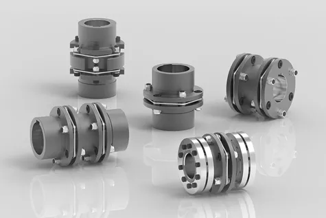
·Product Show
♦Other Products List
| Transmission Machinery Parts Name |
Model |
| Universal Coupling | WS,WSD,WSP |
| Cardan Shaft | SWC,SWP,SWZ |
| Tooth Coupling | CL,CLZ,GCLD,GIICL, GICL,NGCL,GGCL,GCLK |
| Disc Coupling | JMI,JMIJ,JMII,JMIIJ |
| High Flexible Coupling | LM |
| Chain Coupling | GL |
| Jaw Coupling | LT |
| Grid Coupling | JS |
♦Our Company
HangZhou CZPT Machinery Manufacturing Co., Ltd. is a technology-based company specializing in the design and manufacture of basic transmission parts and various auxiliary non-standard equipment accessories. The products are mainly used in metallurgy, electric power, mining, chemical industry, petroleum, papermaking, shipbuilding, heavy industry, etc.
In many industries, it has provided strong technical and equipment support for many companies around the world. At present, the products are also exported to Russia, Italy, Spain, Brazil, Ukraine, Turkey, Australia, Singapore, Vietnam, Indonesia, Malaysia, Sri Lanka, and other countries and regions.
Welcome to customize products from our factory and please provide your design drawings or contact us if you need other requirements.
♦Our Services
1.Design Services
Our design team has experience in cardan shaft relating to product design and development. If you have any needs for your new product or wish to make further improvements, we are here to offer our support.
2.Product Services
raw materials → Cutting → Forging →Rough machining →Shot blasting →Heat treatment →Testing →Fashioning →Cleaning→ Assembly→Packing→Shipping
3.Samples Procedure
We could develop the sample according to your requirement and amend the sample constantly to meet your need.
4.Research & Development
We usually research the new needs of the market and develop the new model when there is new cars in the market.
5.Quality Control
Every step should be special test by Professional Staff according to the standard of ISO9001 and TS16949.
♦FAQ
Q 1: Are you trading company or manufacturer?
A: We are a professional manufacturer specializing in manufacturing
various series of couplings.
Q 2:Can you do OEM?
Yes, we can. We can do OEM & ODM for all the customers with customized artworks of PDF or AI format.
Q 3:How long is your delivery time?
Generally it is 20-30 days if the goods are not in stock. It is according to quantity.
Q 4: Do you provide samples ? Is it free or extra ?
Yes, we could offer the sample but not for free.Actually we have a very good price principle, when you make the bulk order then cost of sample will be deducted.
Q 5: How long is your warranty?
A: Our Warranty is 12 month under normal circumstance.
Q 6: What is the MOQ?
A:Usually our MOQ is 1pcs.
Q 7: Do you have inspection procedures for coupling ?
A:100% self-inspection before packing.
Q 8: Can I have a visit to your factory before the order?
A: Sure,welcome to visit our factory.
Q 9: What’s your payment?
A:1) T/T.
♦Contact Us
Web: huadingcoupling
Add: No.11 HangZhou Road,Chengnan park,HangZhou City,ZheJiang Province,China
Industry Standards and Guidelines for Disc Couplings
Disc couplings, like other mechanical components, are subject to various industry standards and guidelines that ensure their safe and reliable operation. Some relevant standards include:
- API Standard 671: This American Petroleum Institute (API) standard provides guidelines for special-purpose couplings for use in petroleum, chemical, and gas industry services. It covers the design, materials, testing, and inspection of couplings, including disc couplings.
- AGMA Standard 9001: The American Gear Manufacturers Association (AGMA) standard 9001 addresses flexible couplings, including disc couplings, and provides recommendations for their design, installation, and maintenance.
- ISO 14691: This International Organization for Standardization (ISO) standard covers general-purpose industrial couplings, including disc couplings, and provides guidance on their selection, installation, and operation.
Manufacturers and engineers often refer to these standards and guidelines to ensure that disc couplings are designed, manufactured, and used according to recognized industry practices. Adhering to these standards helps enhance the reliability, safety, and performance of disc couplings in various industrial applications.
Customization of Disc Couplings for Specific Machinery Requirements
Disc couplings can indeed be customized to match specific machinery requirements and limitations:
- Size and Configuration: Disc couplings can be tailored in terms of size and disc configuration to accommodate space restrictions and torsional load demands.
- Material Selection: The choice of materials for the disc packs can be customized to ensure compatibility with the operational environment, such as temperature, corrosion resistance, and other factors.
- Performance Parameters: Disc couplings can be designed to meet specific performance parameters, including torque capacity, misalignment accommodation, and torsional stiffness.
- Attachment and Hub Designs: The attachment mechanisms and hub designs can be customized to seamlessly integrate with the existing machinery components.
- Specialized Applications: Manufacturers can create disc couplings with unique features for specialized applications, such as those requiring higher precision, critical alignment, or specific levels of vibration dampening.
Through customization, disc couplings can effectively address the unique requirements and limitations of various machinery systems, enhancing their performance and reliability.
Challenges and Solutions for Misaligned Disc Couplings
Misalignment in disc couplings can lead to several challenges, but these issues can be effectively addressed using appropriate measures:
- Reduced Efficiency: Misalignment can cause increased friction and wear, leading to energy losses and reduced coupling efficiency. Regular maintenance and proper alignment can help mitigate this issue.
- Vibration and Noise: Misalignment often results in vibrations and noise in the machinery. This can impact the overall performance of the system and cause discomfort to operators. Ensuring precise alignment and using vibration-damping solutions can minimize these effects.
- Premature Wear: Disc couplings experiencing misalignment may wear out prematurely due to uneven loading and stress concentrations. Optimal alignment and using coupling models designed to handle misalignment can extend the coupling’s lifespan.
- Imbalanced Loads: Misalignment can lead to imbalanced loads on the coupling discs, causing uneven stress distribution. This can lead to fatigue and failure. Using spacer elements between the discs and proper alignment can distribute the loads more evenly.
- Reduced Accuracy: In applications requiring precision positioning, misaligned disc couplings can result in inaccurate measurements or positioning. Implementing accurate alignment practices and selecting couplings designed for precise applications can mitigate this challenge.
- Temperature Rise: Misalignment-induced friction generates heat, leading to temperature rise in the coupling and adjacent components. This can potentially affect the material properties and lead to premature wear. Proper alignment and selecting appropriate lubrication can manage temperature rise.
Addressing misalignment challenges involves a combination of careful installation, routine maintenance, alignment checks, and using coupling designs that offer flexibility and resilience to misalignment. Regular monitoring and addressing misalignment issues promptly can help ensure the longevity and optimal performance of disc couplings.


editor by CX 2023-09-08